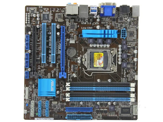
Page 32: P8h67-m pro sata connectors, Aafp, 20 chapter 1: product introduction, Install the windows

View and Download Asus P8H67-M LE user manual online. P8H67-M LE Series. P8H67-M LE Motherboard pdf manual download. Also for: P8h67-m lx, P8h67-m r3.
1-20
Chapter 1: Product introduction
1.10.2
Internal connectors
1.
Front panel audio connector (10-1 pin AAFP)
This connector is for a chassis-mounted front panel audio I/O module that supports
either High Definition Audio or AC`97 audio standard. Connect one end of the front
panel audio I/O module cable to this connector.
P8H67-M PRO
P8H67-M PRO Analog front panel connector
AAFP
PIN 1
GN
D
PRESENCE#
SENSE1_RETUR
SENSE2_RETUR
PORT1
L
PORT1
R
PORT2
R
SENSE_SEN
D
PORT2
L
HD-audio-compliant
pin definition
PIN 1
AGND
NC
NC
NC
MIC2
MICPW
R
Line out_
R
NC
Line out_
L
Legacy AC’97
compliant definition
If you want to connect a high-definition front panel audio module to this connector, ensure
that the Front Panel Type item in the BIOS is set to [HD Audio]. If you want to connect an
AC97 front panel audio module to this connector, set the item to [AC97]. See section 2.5.7
Onboard Devices Configuration for details.
2.
Serial ATA connectors (7-pin SATA3G1-4, 7-pin SATA6G1-2)
These connectors are for the Serial ATA signal cables for Serial ATA 3Gb/s or 6Gb/s
hard disk and optical disk drives.
Install the Windows
®
XP Service Pack 2 or later version before using Serial ATA.
GN
D
RSATA_TXP
1
RSATA_TXN1
GN
D
RSATA_RXP
P8h67 M Pro
1
RSATA_RXN1
GN
D
SATA3G_1
SATA6G_1
SATA3G_2
SATA6G_2
GN
D
RSATA_TXP
2
RSATA_TXN2
GN
D
RSATA_RXP
2
Asus P8h67-m Pro Manual
RSATA_RXN2
GN
D
GN
D
RSATA_TXP
3
P8h67 M Pro Driver
RSATA_TXN3
GN
D
RSATA_RXP
3
RSATA_RXN3
GN
D
SATA3G_3
SATA3G_4
GN
D
RSATA_TXP
4
RSATA_TXN4
GN
D
RSATA_RXP
4
RSATA_RXN4
GN
D
GN
D
RSATA_TXP1
RSATA_TXN1
GN
D
RSATA_RXP1
RSATA_RXN1
GN
D
GN
D
RSATA_TXP2
RSATA_TXN2
GN
D
RSATA_RXP2
RSATA_RXN2
GN
D
P8H67-M PRO
P8H67-M PRO SATA connectors
1-18
Asus P8h67 M Pro Drivers
Chapter 1: Product introduction
1.9
Onboard LEDs
1.
Standby Power LED
The motherboard comes with a standby power LED that lights up to indicate that the
system is ON, in sleep mode, or in soft-off mode. This is a reminder that you should
shut down the system and unplug the power cable before removing or plugging in any
motherboard component. The illustration below shows the location of the onboard LED.
2.
DRAM LED
DRAM LED checks the DRAM in sequence during motherboard booting process. If an
error is found , the LED next to the error device will continue lighting until the problem
is solved. This user-friendly design provides an intuitional way to locate the root
problem within a second.
SB_PWR
ON
Standby Power Powered Off
P8h67 M Pro Motherboard
OFF
P8H67-M LX
P8H67-M LX Onboard LED
P8H67-M LX
Asus P8z77 M Manual
P8H67-M LX DRAM LED
DRAM LED